cobalt123
Platinum Member
Some thoughts on sub-box designs (and other stuff)
Posted on December 23, 2009 by sparky3489
Many people don’t realize that, unless you have virtually unlimited resources, there are going to be trade offs when designing a system. If you want a system to produce a lot of SPL (but have limited power or number of speakers), you’ll probably have to concentrate a lot of the acoustic energy within a small band of frequencies. This would allow you to generate the desired SPL and properly impress your friends. It would, however, leave you with a system that would have less than perfect frequency response and marginal performance at the low frequency end of the spectrum. You could design a system that would produce the desired SPL at all frequencies but it would require significantly more power and speakers than the aforementioned system with the narrow peak.
Installing car stereo equipment is no picnic. Cramming electronics and speakers into places they simply weren’t meant to be presents a challenge to even the most savvy of installers. And the more exotic the install, the tougher the task. While each aspect of system design brings a unique set of challenges to the installation party, building custom speaker enclosures is perhaps the most creative aspect of the installation.
The box-building option is regularly exercised by enthusiasts in pursuit of smooth, deep bass – a tough nut to crack in the automobile environment. Three enclosure types that are practical for most automobile applications are the "sealed box", "vented box" and the "bandpass box". Although different in design and operation, these types utilize the same basic construction techniques. But before you grab a saw and carpenter’s square, you have to decide which box will best suit your needs.
Manufacturers Recommendations:
Many manufacturers recommend an enclosure that’s going to give you a peak like I mentioned earlier. This will give you good results for rap or other bass heavy music. If you listen to those types of music, this system may perform satisfactorily. If you listen to all types of music, you’d likely want an enclosure that would give a flatter response. To get a flatter response, you could increase the size of the enclosure but the overall response wouldn’t be perfectly flat. To build a system that had a perfectly flat frequency response (generally desired by audiophiles), you’ll have to take the vehicle into account. When a manufacturer recommends a particular enclosure, you should ask yourself (or, better yet, the manufacturer) what the enclosure is optimized for.
Enclosure Types:
When laying out a system, you need to decide what type of enclosure to use. No enclosure is magic!
Sealed Enclosures
Straightforward in design, the sealed box is nothing more than an airtight enclosure whose purpose is to enhance speaker performance. When a woofer is installed in one, the sound waves that emanate from the front of the speaker cone are separated from the rear-firing waves. This improves bass response, since opposing waves can cancel each other out when they aren’t isolated. Superb damping, good power-handling capability, and simplicity of construction make the sealed-box enclosure an ideal candidate for a variety of installations. A sealed enclosure will be the smallest (for a given response shape) and will have good low frequency extension but may not have the best low frequency extension. If space is limited, this may be your best choice.
---------- Post added at 06:57 PM ---------- Previous post was at 06:56 PM ----------
Vented Enclosures
Vented enclosures – also known as ported or bass-reflex systems – are more complex than sealed boxes, but the extra construction work required to install a vent has its rewards. Vented boxes are more efficient than their sealed counterparts, since they channel sound waves from the front and rear of the cone into the listening environment. Other virtues of the vented design include better reproduction of low bass, a reasonably flat response curve, and low distortion – provided the box is properly constructed. A vented enclosure will generally have a better low frequency extension for a given response shape (alignment) but would require a larger enclosure. If you made the enclosure as small as the sealed enclosure but ported it to gain the low frequency response, the output would deviate from the desired flat response.
Bandpass Enclosures
A bandpass enclosure can sound good and give you a flat response but most of the generic bandpass enclosures are not designed for a flat response. They are designed to impress you in the stores. This means that they are built to produce a large peak at some frequency near 60hz. These enclosures will work well with something like rap music but generally won’t sound good with other types of music. If you use a bandpass enclosure, it should be designed specifically for your speakers.
If you’re building your first system, I’d recommend a sealed enclosure. It is the simplest enclosure and will be the easiest to get right. A sealed enclosure only needs to be the right size and well sealed. Alright… Enough of my opinions.
System Design
The first step when designing an enclosure is determining how much space is available in your vehicle. If you own a hatchback, for example, calculate the cubic footage of the hatch area, keeping in mind that you’ll still need access to your spare tire. The space available will dictate the size and shape of the enclosure, which in turn will narrow your choice of drivers. For example, one 10-inch subwoofer typically requires an enclosure with 1 to 1.5 cubic feet of internal volume for optimum performance, while a 12-inch subwoofer requires 2 to 3 cubic feet. It’s important to note that any recommendation won’t take into account the volume that will be displaced by the drivers, crossovers, internal braces, and, in the case of a vented system, the port. To compensate for these components, you must build your enclosure slightly larger than your measurements indicate. As a rule of thumb, it’s generally wise to increase the volume by 20%.
When figuring out the shape of your box, keep in mind these "ideal" dimension guidelines: Depth should be 0.7 x Width and Height 1.4 x Width. Also, avoid constructing an enclosure with walls that have equal dimensions; this could result in a resonant peak in the midbass region.
If the enclosure is going to be irregularly shaped – as most are – it’s easiest to think of its interior as a collection of conventional shapes, calculate the volume for each, and add these volumes together. For example, the volume of a box with a slanted front is most easily determined by adding the volume of the square or rectangular portion at the bottom to the volume of the triangular portion at the top. Also, it’s easier to measure in cubic inches and then convert to cubic feet than to work with cubic-foot figures alone.
---------- Post added at 06:57 PM ---------- Previous post was at 06:57 PM ----------
Calculating Speaker Enclosure Volume
As you already know, for speakers (especially woofers) to work properly, they must be in the proper size enclosure. The manufacturer can give you the required enclosure volume but can’t give the exact dimensions of an enclosure that will work in all vehicles. So that you can build an enclosure of the proper size for your vehicle, this page will explain how you calculate the total volume of the enclosure.
Magic number:
OK… It’s not magic but the number is 1728. If you forget it, just remember that the number is 12 inches X 12 inches X 12 inches. 12 X 12 X 12 = 1728.
Square or Rectangular Enclosures:
These boxes are the easiest to calculate the internal volume. You simply measure the height, width and depth (in inches), multiply them together and then divide that number by 1728. If the box has internal measurements of 6" high x 18" wide x 12" deep then the volume of the box is 1296/1728=.75 ft³.
Wedge Enclosures:
Since wedges are comprised of two shapes, a rectangle and a triangle, they are fairly easy to caculate as well. Simply seperate the shapes, and calculate for each. Use the same method above for the internal measurements of a rectangle, then use (H X W X D) / 2 for the triangles internal volume. Add these together to get your total internal volume.

Area (rectangle) = Height x Width
Area (triangle) = 1/2 Height x Width
Area (circle) = 3.141592654 x Radius²
Area (circle) = .7853981634 x Diameter²
Volume (rectangular box) = Area (of one side) x Depth
Volume (triangular enclosure) = Area (triangle) x Depth
Volume (cylinder) = Area (circle) x Depth
1728 Cubic Inches = 1 Cubic Foot
28 Liters = 1 Cubic Foot
If you want to compensate for the volume taken up by the woofer, you can use the following approximations. Keep in mind that these are for ‘normal’ woofers. If you’re using a competition woofer with a huge frame and magnet structure, refer to the manufacturer for the actual displacement volume of the woofer. Even if you’re not using competition woofers, most high quality manufacturers provide this spec in the woofer’s datasheet.
8" = .03 ft³
10" = .05 ft³
12" = .07 ft³
15" = .10 ft³
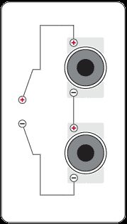
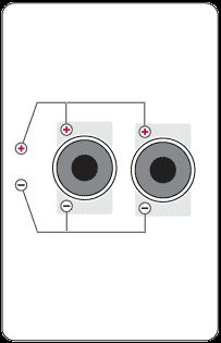
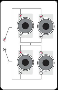
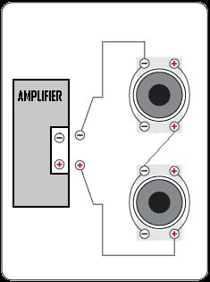
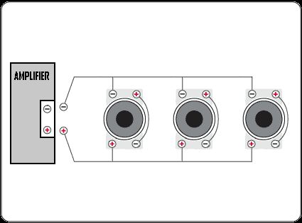
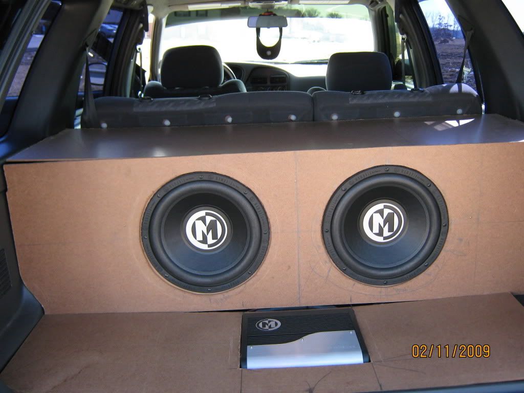
For multiple-driver enclosures, you’ll get the best performance by isolating each driver in a separate chamber. This prevents variations in speaker tolerances and input power from restricting system output. If building separate chambers isn’t feasible, you can make sure that each driver receives the same amount of power by mounting two identical drivers in the same cavity and wiring them in parallel keeping in mind that ths will half the impedance.
Given the extraordinary number of choices, selecting drivers can be a bewildering task. It requires an understanding of specs as well as a sharp set of ears. For some guidance, talk to an experienced installer.
Once you’ve selected an enclosure type and the appropriate drivers, map out the design on paper. This will help you visualize the shape of the enclosure and may prevent unnecessary cutting. Before you take out your trusty saw, be absolutely sure that the enclosure will fit in your
vehicle.
Cautions
If you pick a tuning frequency above the lowest frequency that you intend to drive into the speakers, the speaker may well be damaged due to the lack of damping. Below the tuning frequency, all of the control will depend on the speaker’s suspension. If you drive the amplifier into clipping, the problem will be even worse. If you’re not sure about the proper tuning frequency, use a sealed box or at the very least keep an eye on your woofers for the first few times that you drive them hard with very low notes .
You can not have a port length shorter than the thickness of the wood that you’re using.
I don’t recommend using a port diameter of less than 3 inches for subwoofers.
The port length must be short enough to allow a clearance of the port’s diameter between the end of the port and the wall of the box. If you’re using a 3 inch port, allow at least 3 inches between the back end of the port and any wall of the enclosure.
If you want to use square ports, use a port who’s height multiplied by its width equals the ‘port area’. The port length will be the same as the round port.
Posted on December 23, 2009 by sparky3489
Many people don’t realize that, unless you have virtually unlimited resources, there are going to be trade offs when designing a system. If you want a system to produce a lot of SPL (but have limited power or number of speakers), you’ll probably have to concentrate a lot of the acoustic energy within a small band of frequencies. This would allow you to generate the desired SPL and properly impress your friends. It would, however, leave you with a system that would have less than perfect frequency response and marginal performance at the low frequency end of the spectrum. You could design a system that would produce the desired SPL at all frequencies but it would require significantly more power and speakers than the aforementioned system with the narrow peak.
Installing car stereo equipment is no picnic. Cramming electronics and speakers into places they simply weren’t meant to be presents a challenge to even the most savvy of installers. And the more exotic the install, the tougher the task. While each aspect of system design brings a unique set of challenges to the installation party, building custom speaker enclosures is perhaps the most creative aspect of the installation.
The box-building option is regularly exercised by enthusiasts in pursuit of smooth, deep bass – a tough nut to crack in the automobile environment. Three enclosure types that are practical for most automobile applications are the "sealed box", "vented box" and the "bandpass box". Although different in design and operation, these types utilize the same basic construction techniques. But before you grab a saw and carpenter’s square, you have to decide which box will best suit your needs.
Manufacturers Recommendations:
Many manufacturers recommend an enclosure that’s going to give you a peak like I mentioned earlier. This will give you good results for rap or other bass heavy music. If you listen to those types of music, this system may perform satisfactorily. If you listen to all types of music, you’d likely want an enclosure that would give a flatter response. To get a flatter response, you could increase the size of the enclosure but the overall response wouldn’t be perfectly flat. To build a system that had a perfectly flat frequency response (generally desired by audiophiles), you’ll have to take the vehicle into account. When a manufacturer recommends a particular enclosure, you should ask yourself (or, better yet, the manufacturer) what the enclosure is optimized for.
Enclosure Types:
When laying out a system, you need to decide what type of enclosure to use. No enclosure is magic!
Sealed Enclosures
Straightforward in design, the sealed box is nothing more than an airtight enclosure whose purpose is to enhance speaker performance. When a woofer is installed in one, the sound waves that emanate from the front of the speaker cone are separated from the rear-firing waves. This improves bass response, since opposing waves can cancel each other out when they aren’t isolated. Superb damping, good power-handling capability, and simplicity of construction make the sealed-box enclosure an ideal candidate for a variety of installations. A sealed enclosure will be the smallest (for a given response shape) and will have good low frequency extension but may not have the best low frequency extension. If space is limited, this may be your best choice.
---------- Post added at 06:57 PM ---------- Previous post was at 06:56 PM ----------
Vented Enclosures
Vented enclosures – also known as ported or bass-reflex systems – are more complex than sealed boxes, but the extra construction work required to install a vent has its rewards. Vented boxes are more efficient than their sealed counterparts, since they channel sound waves from the front and rear of the cone into the listening environment. Other virtues of the vented design include better reproduction of low bass, a reasonably flat response curve, and low distortion – provided the box is properly constructed. A vented enclosure will generally have a better low frequency extension for a given response shape (alignment) but would require a larger enclosure. If you made the enclosure as small as the sealed enclosure but ported it to gain the low frequency response, the output would deviate from the desired flat response.
Bandpass Enclosures
A bandpass enclosure can sound good and give you a flat response but most of the generic bandpass enclosures are not designed for a flat response. They are designed to impress you in the stores. This means that they are built to produce a large peak at some frequency near 60hz. These enclosures will work well with something like rap music but generally won’t sound good with other types of music. If you use a bandpass enclosure, it should be designed specifically for your speakers.
If you’re building your first system, I’d recommend a sealed enclosure. It is the simplest enclosure and will be the easiest to get right. A sealed enclosure only needs to be the right size and well sealed. Alright… Enough of my opinions.
System Design
The first step when designing an enclosure is determining how much space is available in your vehicle. If you own a hatchback, for example, calculate the cubic footage of the hatch area, keeping in mind that you’ll still need access to your spare tire. The space available will dictate the size and shape of the enclosure, which in turn will narrow your choice of drivers. For example, one 10-inch subwoofer typically requires an enclosure with 1 to 1.5 cubic feet of internal volume for optimum performance, while a 12-inch subwoofer requires 2 to 3 cubic feet. It’s important to note that any recommendation won’t take into account the volume that will be displaced by the drivers, crossovers, internal braces, and, in the case of a vented system, the port. To compensate for these components, you must build your enclosure slightly larger than your measurements indicate. As a rule of thumb, it’s generally wise to increase the volume by 20%.
When figuring out the shape of your box, keep in mind these "ideal" dimension guidelines: Depth should be 0.7 x Width and Height 1.4 x Width. Also, avoid constructing an enclosure with walls that have equal dimensions; this could result in a resonant peak in the midbass region.
If the enclosure is going to be irregularly shaped – as most are – it’s easiest to think of its interior as a collection of conventional shapes, calculate the volume for each, and add these volumes together. For example, the volume of a box with a slanted front is most easily determined by adding the volume of the square or rectangular portion at the bottom to the volume of the triangular portion at the top. Also, it’s easier to measure in cubic inches and then convert to cubic feet than to work with cubic-foot figures alone.
---------- Post added at 06:57 PM ---------- Previous post was at 06:57 PM ----------
Calculating Speaker Enclosure Volume
As you already know, for speakers (especially woofers) to work properly, they must be in the proper size enclosure. The manufacturer can give you the required enclosure volume but can’t give the exact dimensions of an enclosure that will work in all vehicles. So that you can build an enclosure of the proper size for your vehicle, this page will explain how you calculate the total volume of the enclosure.
Magic number:
OK… It’s not magic but the number is 1728. If you forget it, just remember that the number is 12 inches X 12 inches X 12 inches. 12 X 12 X 12 = 1728.
Square or Rectangular Enclosures:
These boxes are the easiest to calculate the internal volume. You simply measure the height, width and depth (in inches), multiply them together and then divide that number by 1728. If the box has internal measurements of 6" high x 18" wide x 12" deep then the volume of the box is 1296/1728=.75 ft³.
Wedge Enclosures:
Since wedges are comprised of two shapes, a rectangle and a triangle, they are fairly easy to caculate as well. Simply seperate the shapes, and calculate for each. Use the same method above for the internal measurements of a rectangle, then use (H X W X D) / 2 for the triangles internal volume. Add these together to get your total internal volume.

Area (rectangle) = Height x Width
Area (triangle) = 1/2 Height x Width
Area (circle) = 3.141592654 x Radius²
Area (circle) = .7853981634 x Diameter²
Volume (rectangular box) = Area (of one side) x Depth
Volume (triangular enclosure) = Area (triangle) x Depth
Volume (cylinder) = Area (circle) x Depth
1728 Cubic Inches = 1 Cubic Foot
28 Liters = 1 Cubic Foot
If you want to compensate for the volume taken up by the woofer, you can use the following approximations. Keep in mind that these are for ‘normal’ woofers. If you’re using a competition woofer with a huge frame and magnet structure, refer to the manufacturer for the actual displacement volume of the woofer. Even if you’re not using competition woofers, most high quality manufacturers provide this spec in the woofer’s datasheet.
8" = .03 ft³
10" = .05 ft³
12" = .07 ft³
15" = .10 ft³
For multiple-driver enclosures, you’ll get the best performance by isolating each driver in a separate chamber. This prevents variations in speaker tolerances and input power from restricting system output. If building separate chambers isn’t feasible, you can make sure that each driver receives the same amount of power by mounting two identical drivers in the same cavity and wiring them in parallel keeping in mind that ths will half the impedance.
Given the extraordinary number of choices, selecting drivers can be a bewildering task. It requires an understanding of specs as well as a sharp set of ears. For some guidance, talk to an experienced installer.
Once you’ve selected an enclosure type and the appropriate drivers, map out the design on paper. This will help you visualize the shape of the enclosure and may prevent unnecessary cutting. Before you take out your trusty saw, be absolutely sure that the enclosure will fit in your
vehicle.
Cautions
If you pick a tuning frequency above the lowest frequency that you intend to drive into the speakers, the speaker may well be damaged due to the lack of damping. Below the tuning frequency, all of the control will depend on the speaker’s suspension. If you drive the amplifier into clipping, the problem will be even worse. If you’re not sure about the proper tuning frequency, use a sealed box or at the very least keep an eye on your woofers for the first few times that you drive them hard with very low notes .
You can not have a port length shorter than the thickness of the wood that you’re using.
I don’t recommend using a port diameter of less than 3 inches for subwoofers.
The port length must be short enough to allow a clearance of the port’s diameter between the end of the port and the wall of the box. If you’re using a 3 inch port, allow at least 3 inches between the back end of the port and any wall of the enclosure.
If you want to use square ports, use a port who’s height multiplied by its width equals the ‘port area’. The port length will be the same as the round port.


